
RJW Electrical
What does control panel wiring involve in a three-phase installation?
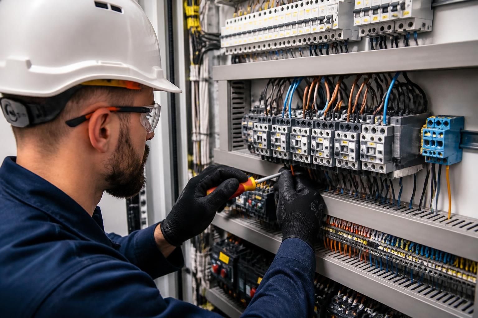
Three-phase control panel wiring involves selecting and arranging the protective devices, switching equipment, control components and terminals needed to operate a three-phase system safely. The installer then connects the power and control circuits, labels the wiring, checks phase identification and carries out inspection and testing before the panel is put into service.
Control panel wiring in a three-phase installation is the engineered arrangement of incoming supply connections, protective equipment, switching devices, control circuits and outgoing terminals within an enclosure. The wiring must allow the connected equipment to operate in the intended sequence while managing fault protection, isolation, phase relationships, heat, accessibility and future maintenance.
Design starts with the load and control requirements. The panel design is based on the equipment it will operate, such as motors, pumps, compressors, heaters or production machinery. Important information includes the full-load current, starting current, duty cycle, method of starting, control voltage, number of controlled devices and any required interlocks. This determines the ratings of the incoming switchgear, protective devices, contactors, overload protection, terminals and outgoing cables.
The designer also considers the prospective fault current at the panel and whether the protective devices have suitable breaking capacity. Devices should be coordinated so that a fault is disconnected safely and, where the design permits, the affected circuit is isolated without unnecessarily interrupting other parts of the installation. Cable sizes and protective settings must be compatible with the equipment and the installation conditions.
Power and control wiring have different functions. Power wiring carries the three-phase supply to the load, while control wiring operates contactors, relays, sensors, timers, safety devices or other control equipment. A control circuit may use a separate voltage from the incoming three-phase supply, provided it has suitable protection, isolation and identification. Control transformers, power supplies and protective fuses may therefore form part of the panel arrangement.
Keeping higher-power conductors separate from sensitive control and signal wiring helps reduce unwanted interference and makes fault-finding easier. Where cables cross or share trunking, the arrangement should follow the requirements of the equipment and the applicable wiring standards. Terminals, cable entries and enclosure components must also maintain the required level of protection against contact, dust or moisture for the installation environment.
Motor circuits require particular attention. A motor starter may include a circuit breaker or switch-fuse, contactor and thermal or electronic overload relay. The overload protection is set in accordance with the motor and manufacturer’s requirements, rather than simply selected from the cable size. The control circuit may include start and stop stations, a holding contact, an emergency-stop circuit, limit switches or process interlocks.
Where a motor is connected directly to the three-phase supply, the phase sequence affects its direction of rotation. If the application requires a particular direction, this is checked during commissioning and corrected using an approved method. Incorrect rotation can damage machinery or produce an unsafe operating condition. Applications requiring controlled acceleration or speed adjustment may instead use a soft starter or variable-speed drive, with wiring and protective measures appropriate to that equipment.
Physical construction affects safety and reliability. Components need sufficient space for bending radii, termination and heat dissipation. Protective devices and isolators should be accessible and clearly identified, while high-energy parts should not be exposed during routine operation. Conductors are normally routed neatly, supported appropriately and terminated so that there is no undue strain on terminals.
Each conductor should be identified consistently with the circuit drawings and terminal schedule. Protective conductors require dependable continuity, and neutral conductors must not be confused with phase conductors. The arrangement should also make it possible for a competent person to isolate the correct section before inspection, testing or maintenance. Unused entries and openings should be closed with suitable components so the enclosure retains its intended protection.
Testing covers more than checking whether the equipment runs. Before energisation, the installation is inspected for correct component ratings, secure terminations, conductor identification, protective bonding, separation of circuits and signs of damage. Electrical tests can include continuity of protective conductors, insulation resistance, polarity and verification of automatic disconnection conditions, as applicable to the design.
Once these checks are satisfactory, functional testing confirms that switches, contactors, overload devices, emergency stops, interlocks, indicators and connected equipment work in the intended order. Three-phase systems also require verification of phase sequence where rotation matters. Results should be recorded alongside the circuit diagrams, settings, test information and any operating instructions needed by the person responsible for the installation.
For a commercial or industrial control panel, the quality of the wiring is therefore determined by both the electrical connections and the engineering behind them. A correctly designed panel protects people and equipment, provides predictable control of the three-phase load and gives future users enough information to operate, inspect and maintain the system safely.
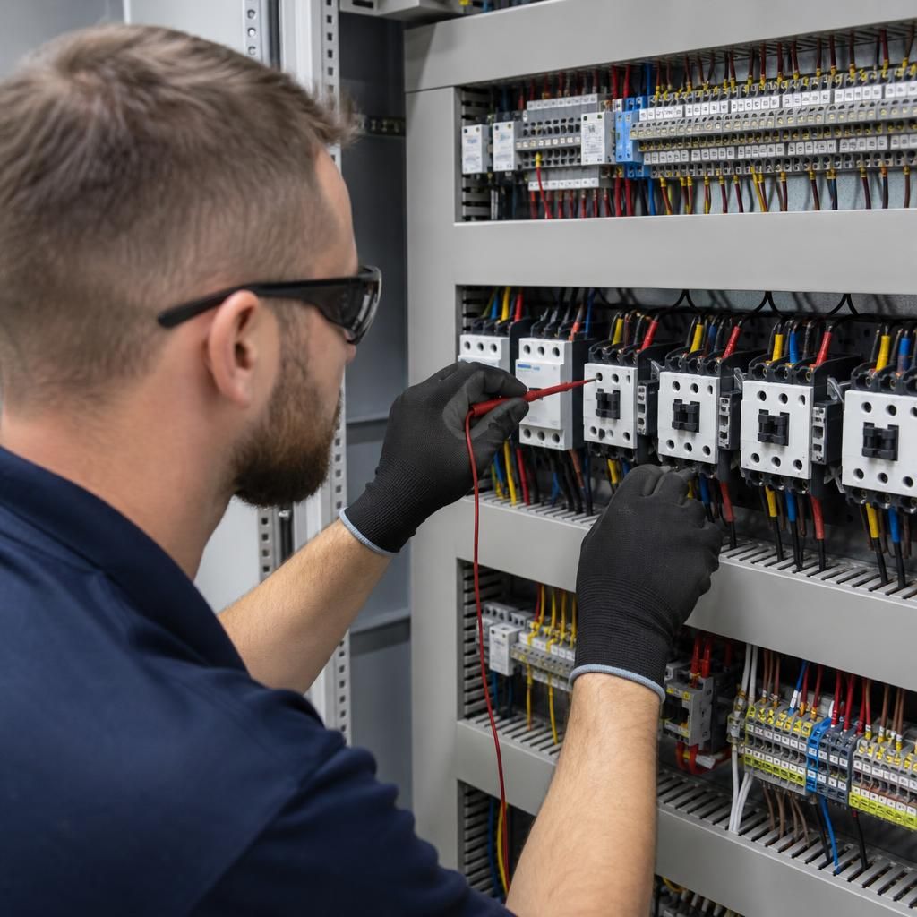
A key part of three-phase control panel wiring is creating a control circuit that allows equipment to operate in the correct sequence and prevents unsafe commands from being carried out. The control circuit may use push buttons, selector switches, sensors, relays and auxiliary contacts to determine when the main contactors can energise.
Interlocking is used where two actions must not happen together. For example, forward and reverse motor contactors can be arranged so that energising one prevents the other from closing. Electrical interlocks provide this protection through auxiliary contacts, while mechanical interlocks may provide an additional safeguard between compatible contactors.
Safety controls are commonly designed to move the circuit to a de-energised state when a fault, emergency stop or broken control connection occurs. Emergency-stop devices, guard switches and overload contacts are therefore incorporated into the control logic rather than treated as separate accessories. A reset may be required before the equipment can restart, helping prevent unexpected operation after power is restored.
This arrangement means the panel wiring must reflect the intended operating sequence clearly. The circuit drawings, terminal references and device labels should correspond with the physical wiring so that the controls can be understood and checked by a competent person without relying on assumptions about how the machinery is meant to operate.
Discuss Your Three-Phase Control Panel Wiring Requirements
If you are planning a three-phase control panel installation or modification, discuss your requirements with RJW Electrical and request a no-call-out-fee quote based on the equipment, controls and operating sequence involved.